U.S. Energy Efficient Requirements for Electric Motors
Did you know that new energy efficiency regulations for induction (AC) motors sold and installed in the United States were introduced on June 1st, 2016?
The new regulations expand the scope of the Energy Independence and Security Act (“EISA”) of 2007 which required most induction motors sold after December of 2010 to meet NEMA Premium® efficiency levels. The expanded efficiency requirements are referred to as either the “EISA Expansion” or the “Integral Horsepower Rule”, the U.S. Department of Energy “Final Rule” passed into law on May 29th, 2014. The “EISA Expansion” does not define a new standard for motor energy efficiency, but instead expands the established requirement for NEMA Premium® efficiency to a broader range of induction motor types. Significant expansions include the addition of 6- and 8-Pole motors, continuous-duty brake motors, immersible motors and IEC Frame 100 motors. The expanded regulation closes many “loopholes” in the EISA legislation and consequently the vast majority of induction motors sold after June 1st, 2016 in the U.S. must (by law) meet or exceed the applicable NEMA Premium® efficiency level. Why make the change? It’s a matter of dollars and sense. The DoE estimates direct operational cost savings from increased efficiency “EISA Expansion” motors purchased during the period 2016 – 2045 to fall somewhere between US$18.2 – 41.4B. To accommodate these new regulations Lafert North America now offers an expanded AMPH Series of motors, which carry UL Energy Verified marking to certify NEMA Premium® efficiency.
Additional information regarding the recent “EISA Expansion” can be found in the excellent presentation available here, provided by the Electrical Apparatus Service Association (EASA).
IE4/IE5 - Efficiency Ahead of its Time!
Combination of AC Motor’s Reliability and Brushless Servomotor's Performance
Don’t wait for the future – it’s here NOW!
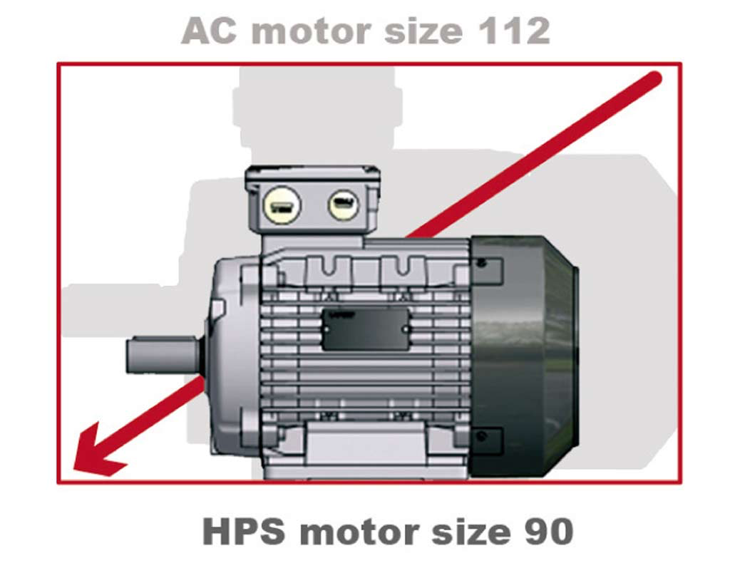

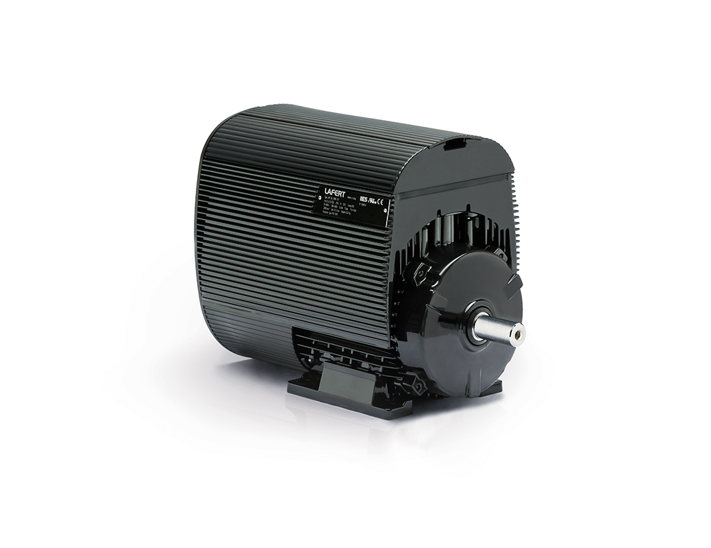
High Performance Motors (HP) is an innovative range of PM (Permanent Magnet) Synchronous Motors, achieving IE4 and even IE5 Super Premium Efficiency level, that offers improved efficiency and reduced operating costs.
This uniquely engineered product combines the electrical design of Brushless Servomotors with the mechanical design of AC Induction Motors. The result is a compact motor range primarily targeted toward HVAC applications in pumps, fans, compressors, and blowers, where there is an emphasis on reducing the operating cost or weight and size of the motors.
The complete range 0.55 kW to 30 kW are supplied as stand-alone motors (HPS range) to be controlled by a separate drive or as motor/drive integrated units (HPI range), specifically designed for their energy saving potential.
STANDARD SPECIFICATIONS
- Wide power output 0.55 - 30 kW
- Compact range in IEC frames: 71 - 90 - 112 - 132
- Voltage: 3 phase 230 - 480 V
- Speed range up to 6000 RPM
- Designed for different magnetic materials to secure stable cost base
- Sensorless control or with speed transducer
- IPM design (no rare earth magnets) or SMPM design (high flux rare earth magnets) depending on the performance demand
- Controlled by most standard Drives

WHAT ARE "IP" RATINGS ALL ABOUT?
Ingress Protection (IP) rating is a sequence of codes used to define a specific level of protection. The code consists of “IP”, followed by two numerical digits, and an optional letter. The first digit represents the level of solids protection, while the second digit represents the level of liquids protection.
Some of the different types of protection levels are as follows; preventing the intrusion of solid objects and liquids from entering an enclosure or motor. Solid objects could include body parts such as hands and fingers, or dust and debris. Liquids may involve oils, moisture and/or condensation.
The IP ratings were designed to provide comprehensive information regarding the intensity of the overall protection for the users’ safety and overall knowledge of their equipment.
Lafert North America’s Stainless Steel Motors are available in IP56, IP67 or IP69K Rating
(IP54 & IP55 available for Standard Aluminum Motors)
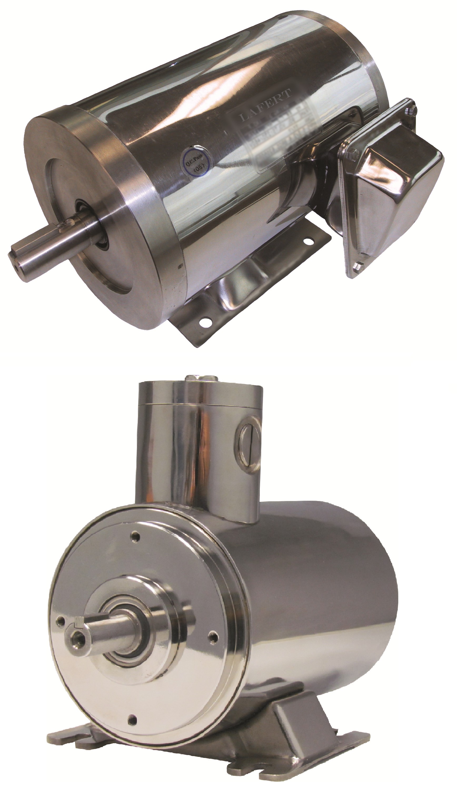
Our IP56 rated Stainless Steel Motor is protected from total dust ingress, and is protected from low pressure water jets sprayed from any direction, or anything else with that same effect.
Our IP67 rated Stainless Steel Motor has one of the highest levels of protection, which is total dust ingress, and protection from immersions between 15 centimeters and 1 meter in depth.
The highest level of protection is the IP69K, which gives you a protection from total dust ingress the same as every IP rated motor, but it will also stay protected from a steam jet clean.
IP Terms Defined:
First Digit – Solids
|
Level 0 |
No protection provided. |
|
Level 1 |
>50mm, protects any large surface of the body, such as the back of a hand, but not deliberate contact. |
|
Level 2 |
>12.5mm, protects fingers or similar sized objects (pencils or pens). |
|
Level 3 |
>2.5mm, protection from possible ingress of tools or thick wires. |
|
Level 4 |
>1mm, protection against ingress of most wires and screws. |
|
Level 5 |
Dust protection: Ingress of dust is not entirely prevented, but dust cannot interfere with the satisfactory operation of the equipment. |
|
Level 6 |
Dust tight; complete protection against ingress of dust. |
Second Digit – Liquids
|
Level 0 |
No protection provided. |
|
Level 1 |
Dripping water, falling vertically will have no harmful effect. This level means it must pass a test duration of 10 minutes, with water dripping equivalent to 1mm rainfall per minute. |
|
Level 2 |
Dripping water, while tilted up to 15 degrees will have no harmful effects. This level means it must pass a test duration of 10 minutes, with water dripping equivalent to 3mm rainfall per minute. |
|
Level 3 |
Spraying water at an angle of up to 60 degrees from vertical will have no harmful effects. This level means it must pass a test duration of 5 minutes, with a water volume of 0.7 liters per minute, with pressure of 80â€100 KN/m2 |
|
Level 4 |
Water that is splashed against the enclosure from any direction will have no harmful effects. This level means it must pass a test duration of 5 minutes, with a water volume of 10 liters per minute, and a pressure of 80â€100 KN/m2 |
|
Level 5 |
Water jets by a 6.3mm nozzle aimed at an enclosure from any direction will have no harmful effects. This level means it must pass a test duration for a minimum of 3 minutes, with a water volume of 12.5 liters per minute, and a pressure of 80â€100KN/m2 |
|
Level 6 |
Powerful water jets from a 12.5mm nozzle, aimed at an enclosure from any direction, will have no harmful effects. This level means it must pass a test duration of 3 minutes minimum, with a water volume of 100 liters per minute, with a pressure of 100KN/m2, at a distance of 3 meters. |
|
Level 6K |
Powerful water jets with increased pressure, water projected in powerful jets (6.3 mm nozzle) against the enclosure from any direction, under elevated pressure, shall have no harmful effects. |
|
Level 7 |
Ingress of water in harmful quantity shall not be possible when the enclosure is immersed in water under defined conditions of pressure and time (up to 1 m of submersion). |
|
Level 8 |
Immersion beyond 1m. The equipment is suitable for continuous immersion in water under conditions which shall be specified by the manufacturer. However, with certain types of equipment, it can mean that water can enter but only in such a manner that it produces no harmful effects. |
|
Level 9K |
Powerful high temperature water jets, protected against close-range high pressure, high temperature spray downs. (detailed specifications/test characteristics provided below) |
Specifications of IP69K
The German standard DIN 40050-9 extends the IEC 60529 rating systems described above with an IP69K rating for high temperature/high-pressure wash-down applications. These ratings typically involve enclosures.
These IP69K enclosures must be dust tight (IP6X), and be able to endure high-pressure steam cleaning, often used in pharmaceutical and food applications.
The high-temperature/high-pressure test specifies a spray nozzle that is fed with 80°C water at 8-10MPa (80-100bar) and a flow rate of 14-16L/min. The spray nozzle is held 10-15 cm from the tested device, at several angles: 0°, 40°, 60°, and 90° for 30 seconds each. The test device is placed on a turntable that rotates once every 12 seconds (5RPM) as the test is performed.
Sources
* https://en.wikipedia.org/wiki/IP_Code
*IP, NEMA and UL Rating Codes, 910 East Orangefair Lane, Anaheim, CA 92801 USA
- https://webcache.googleusercontent.com/search?q=cache:SwoF-qDlRL8J:https://www.anaheimautomation.com/manuals/forms/NEMA,%2520UL,%2520and%2520IP%2520Rating%2520Codes.pdf+&cd=1&hl=en&ct=clnk&gl=ca
Reversing a Single Phase Motor
For a lot of applications, it is important for the motor to run “the right way” and sometimes out of the box the motor doesn’t run in the direction you need.
Laferts' line of single phase motors are typically set up to run clockwise (when facing the shaft) but if a counter-clockwise rotation is desired, it can be done by a simple change to the way the windings are connected on the terminal block.
There are a couple of different ways to do this depending on the type of single phase motor being used.
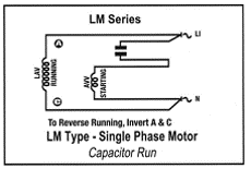
LM motors are a capacitor run type motor which requires swapping the leads in the terminal block marked A and C (the run winding leads) per the attached diagram. These motors are typically used in applications where initial startup torque is not crucial.
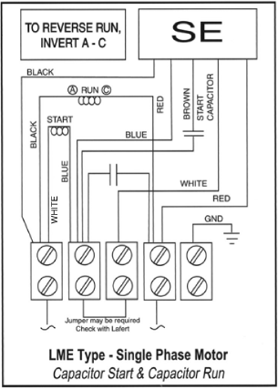
LME motors are a capacitor start and capacitor run style which uses a solid state relay and start capacitor to provide full start up torque. Some manufacturers motors simply need the input leads to be reversed to change the direction of the shaft rotation but due to the relay in the Lafert motors, reversing your input power leads will have no effect on the rotation of the motor so changing the leads on the terminal block is necessary. As per the diagram below, again the A and C marked leads (the run winding) will need to be swapped in the terminal block for the motor to run counterclockwise.
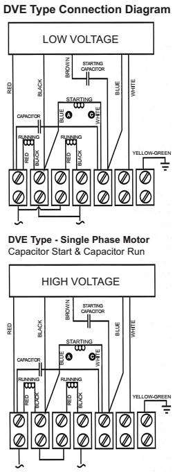
Dual Voltage single phase motors are a versatile choice for any application where the end user would benefit from having the option of running either 115V or 230V on site as well as full start up torque. This style of motor can be configured to run on either voltage by changing the way the terminals are connected on the line side of the terminal block. Reversal of the shaft rotation is accomplished by swapping the start winding leads marked “A” and “C” per the diagram below.
Dual Voltage single phase motors are a versatile choice for any application where the end user would benefit from having the option of running either 115V or 230V on site as well as full start up torque. This style of motor can be configured to run on either voltage by changing the way the terminals are connected on the line side of the terminal block. Reversal of the shaft rotation is accomplished by swapping the start winding leads marked “A” and “C” per the diagram below.
- Scott Thomas, Lafert NA Plant Manager
Why does Lafert offer 796 and 990V motors?
Lafert offers motors with voltages in excess of 600V for specific reasons. Firstly, some industries have specialized applications utilizing higher voltages in order to reduce current values. Secondly and more important to the general industry, it is for the availability of 460 or 575-volt, Delta motor connections.
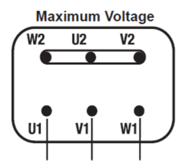
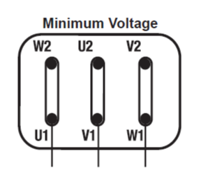
With any standard single speed 6 lead motors, the Wye connection is for High Voltage and the Delta connection is for Low voltage supply to the motor. The variance between the 2 voltages is 1.732. (460V x 1.732 = 796V).
Wye / Delta Starting
With conventional across the line starting, standard motors may draw up to 7 time the rated current as inrush current on startup. As industry standards have moved to High and then Premium efficient motors this inrush current has climbed to as much as 12 time the rated current on start up. Depending on the application and voltage feed to your facility, this can have detrimental effect to your system.
The advantage of utilizing a Wye / Delta start method is to reduce the inrush current and lower the mechanical impact when starting your system. This reduces the added costs of a conventional soft starter, which is used to achieve the result.
Wye / Delta starting can be applied to any Delta / Wye motor regardless of the connection voltages.
How it works
The motor is started with the controls creating a Wye connection to the motor, while applying 460V to the motor. This supplies a lower than rated voltage to the motor, resulting in a softer start and lower inrush current. The motor is brought up to a predetermined speed or current. The controls are then switched to a Delta connection with the same 460V being applied. The motor is now receiving full voltage for the connection and is brought up to full speed and power.
Start in Wye connection.
(Connections made in control panel not at the motor)
Switch to Delta connection to run the motor.
(Connections made in control panel not at the motor)
One important factor to consider is that the rated - Delta voltage of the motor is equivalent to the supply voltage. An alternate means of dealing with a higher inrush current is by switching to a longer time delayed fuse. This allows the motor more time to come up to speed and decrease the amperage draw before tripping breakers or blowing fuses.
If you have any questions, please feel free to contact a Lafert sales personnel.
- Gerald O’Reilly, General Manager
Metric Motor - Mounting Options
There are many mounting options available when ordering a motor through Lafert North America. Knowing the differences between the available options is imperative to ensure the required style of mounting is correctly ordered.
It is important to note that most metric motor manufacturers in North America do not indicate the mounting style of the motor on the name plate. You will need to look at the overall physical motor and not just the name plate to determine what type of mounting style is required. Confirming measurements of both the flange and the motor is also instrumental.
The summary and pictures below explain the differences between the 5 different mounting options.
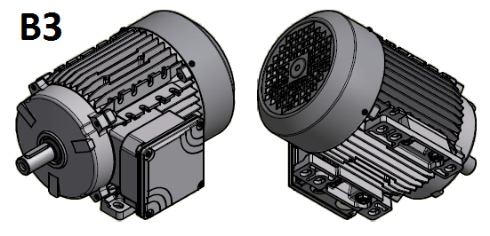
B3: The B3 mounting option indicates that the motor is mounted by its feet only. The motor does not have a mounting flange on the drive end and instead keeps the standard end bell.
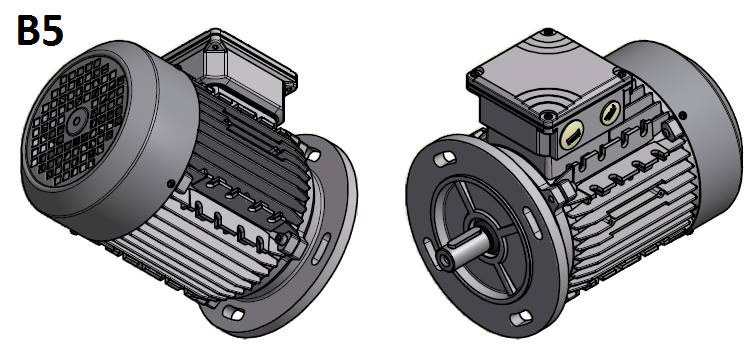
B5: The B5 mounting option indicates that the motor is mounted by a B5 flange only. The B5 flange has slotted mounting holes on the front of the flange. The B5 flange has an increased lip, making the flange larger in diameter than the size of the motor. The motor does not have mounting feet and is a round body motor.
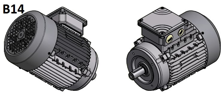
B14: The B14 mounting option indicates that the motor is mounted by a B14 flange only. The B14 flange has threaded mounting holes on the front of the flange. The B14 flange has a smaller lip and is smaller than the B5 flange. The motor does not have mounting feet and is a round body motor.
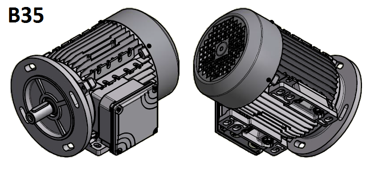
B35: The B35 mounting option is a combination of two mounting styles. The motor is mounted by its feet (B3), as well as being mounted by a B5 flange, thus the B35. The flange has slotted holes on the front to mount to the application, as well as feet to provide excellent stability.
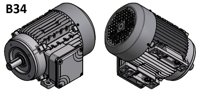
B34: The B34 mounting option is a combination of two mounting styles. The motor is mounted by its feet (B3), as well as being mounted by a B14 flange, thus the B34. The flange has threaded holes on the front to mount to the application, as well as feet to provide excellent stability.
The Importance of Measuring your Motor Shaft
It is a common practice to send a picture of a motor nameplate in when requesting a quotation. While the motor nameplate will help identify the type of motor along with the motor specifics (such as its frame size, HP/KW, RPM, IP rating, etc.), the motor nameplate does not make any reference to the shaft of the motor, as it is not an industry standard. Did you know metric motors of the same frame size could have different shaft dimensions?
Since there is a standard dimension for both the shaft diameter and shaft length for each motor frame size, custom made or modified shafts are a possibility in our ever-growing industry. A motor shaft could have an increased or decreased diameter or length. Shafts can also have a step down which results in two different diameter sizes on the same shaft.
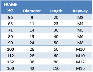
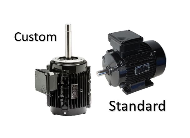
Here is an example of two motors with different shaft dimensions. Both motors share the same motor type on their respective nameplates (ST71S4), and both share the same motor specifications (KW, voltage, HZ, etc.). As you can tell by the picture, the shafts are different. The standard shaft has a 14mm diameter and a 30mm length with a 5mm by 5mm keyway. The below custom shaft has a total length of 150mm, a diameter of 19mm, with a step down for the final 20mm of the shaft going down to a 15mm diameter. This custom shaft has no keyway.
Standard Shaft Dimensions
 It is also possible that your motor could have a non-drive end shaft, pictured below.
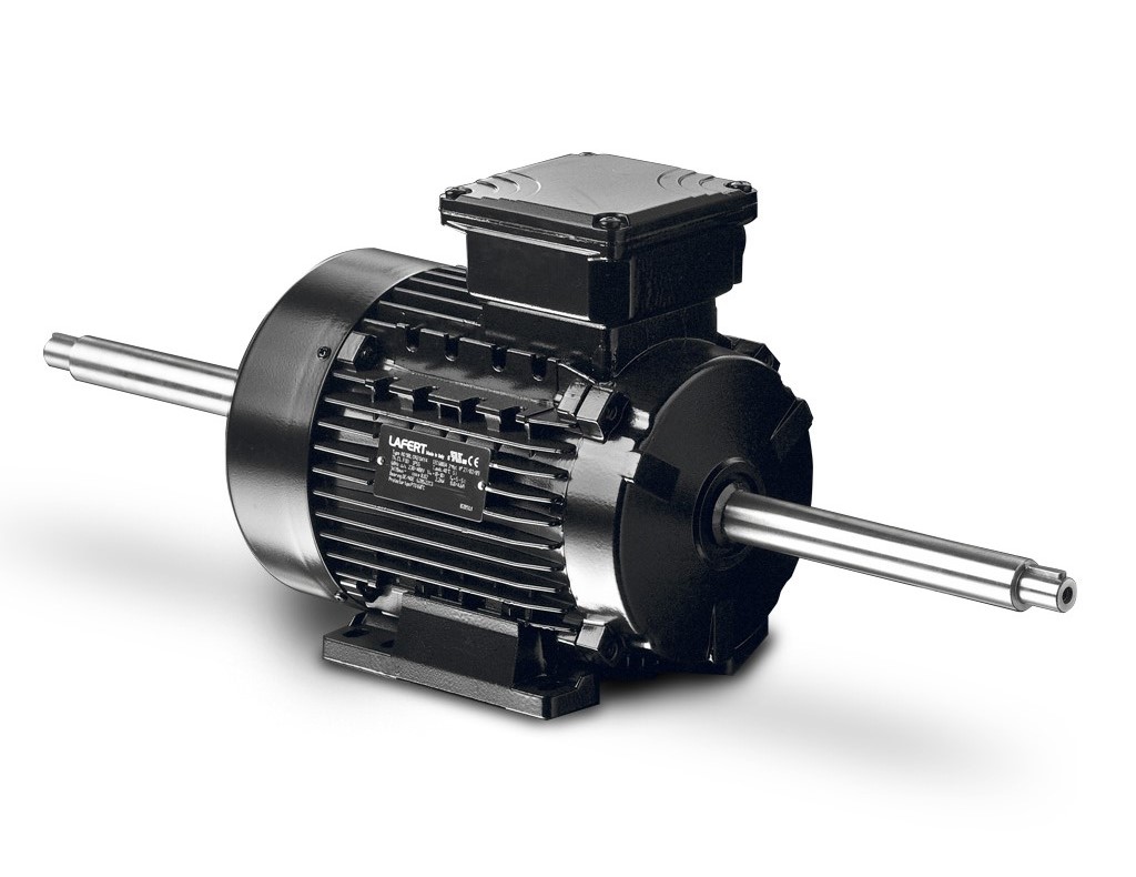
If you rely solely on the motor nameplate and do not check your motors dimensions, you could find yourself ordering the incorrect motor. To avoid frustrated customers, delays in delivery and unnecessary added expenses, always remember to measure the shaft of your motor.
- Paolo Zaffino, Inside Sales
Single Phase Options with Lafert North America
In the motor industry, Lafert North America is known for high quality metric motors and our ability to produce custom motors with a short turnaround time.
Lafert supplies a full range of single phase LM(E) 2 pole (3600rpm), 4 pole (1800rpm) and 6 pole (1200rpm) motors ranging from a 56 frame to a 112 frame, in single voltage 115v or 230v or the DVE duel voltage 115v&230v. The range of Single-Phase Motors is designed specifically to deliver high performance with low levels of vibration and noise.
LM type motors are designed for ‘no load’ or low starting torque applications, such as fan duty. These motors have two windings connected in parallel with a run capacitor, connected in series providing high power factor.
LME type motors are designed for high torque applications. The motors feature capacitor start and capacitor run, making them suitable for most applications (i.e. Gearboxes, pumps, machine tools).
The LME range of single phase motors are capacitor start / run from 0.18kw through to 3.7kw in 2, 4 and 6 pole. These motors have high starting torque and the switching is done by a solid-state electronic relay, instead of a centrifugal switch. The electronic relay senses the voltage drop across the run capacitor as the motor picks up speed and adjusts its switching time automatically, depending on the load to switch the start capacitor out of the circuit at the peak of the torque curve.
The main feature of this product is that the motor is in the same frame size as the equivalent HP in three phase. Also, the motor is the same length as the equivalent three phase motor.
Having our Head office out of Mississauga, Ontario and five strategically located warehouses covering the continental U.S., enables Lafert to provide superior service to meet our customers ever changing Metric needs. Our extensive stock includes Single & Three Phase Motors, Brake Motors, Coolant Pumps, Stainless Steel and Explosion Proof Motors.
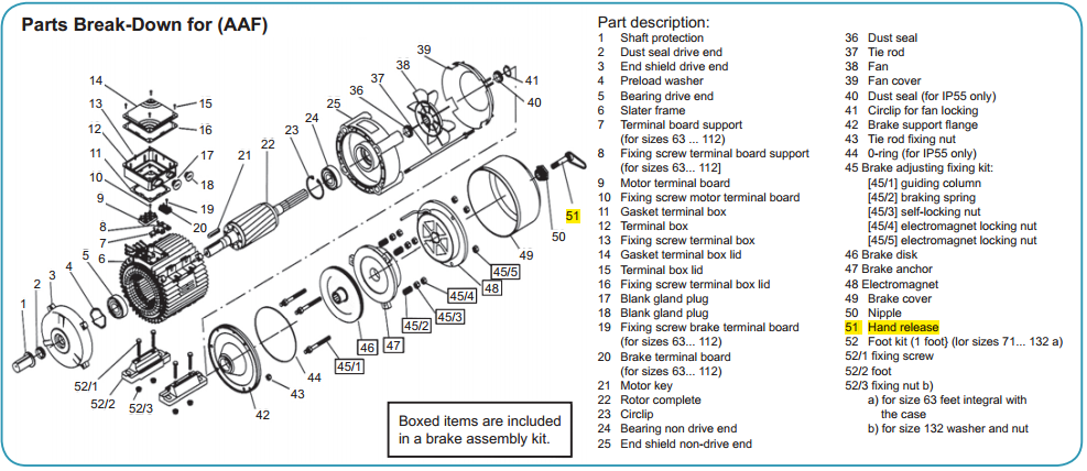
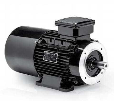
Lafert BRAKE MOTORS
Did you know that Lafert offers a variety of brake motors? We can ship our standard motors from our stock, or we can customize a brake motor to suit your unique requirements.
For an overview of our line of brake motors DOWNLOAD: Brake Motors Presentation 2016
Current Stock of Brake Motors at Lafert North America
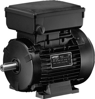
AMS-DC Brake Coil: Compact design with similar dimensions as a standard non brake motor
- Low braking torque
- Slower reaction time than the AAF or AMBZ models
- DC rectified brake coil
- Standard coils are matched to the motor voltage, other options available including custom voltages for unique applications
- Brake coils are single voltage input
- Standard motors supplied with AC to DC rectifiers
​Options are available for fast acting rectifiers for improved reaction time.
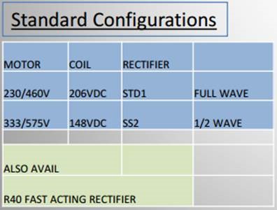

The half wave rectifiers also reduce the input voltage by 50%; an input of 333VAC will be cut in half and reduced by the 15% mentioned above, resulting in approximately 148VDC output.
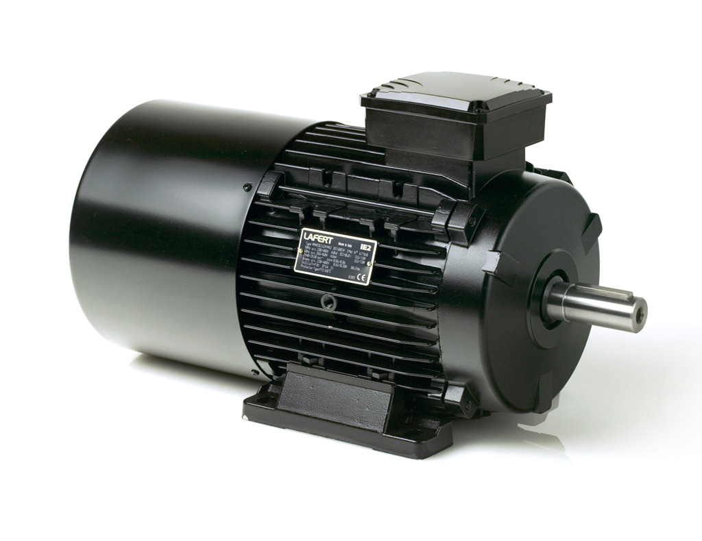
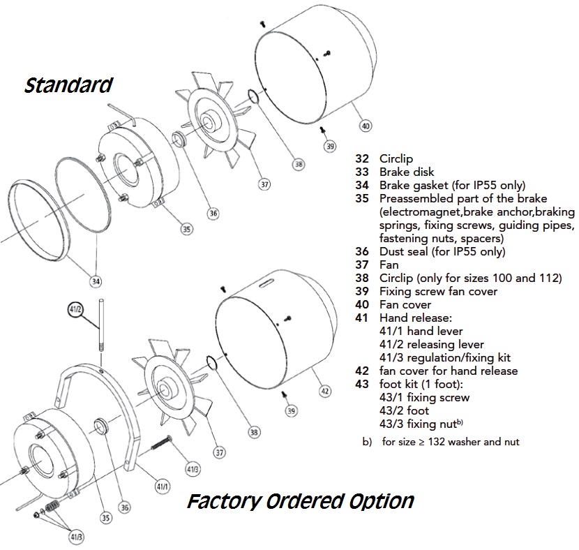
The AAF series brake motors are longer than a standard motor and have two terminal blocks inside the connection box; one for the motor and one for the brake. Larger motors may have a separate box (132 and larger) for the brake only. Brake coils are available in multiple voltages in AC and DC. Brakes can be wired with the motor for simultaneous operation, or separately to operate independently of motor. As a standard, the brake voltage matches the motor voltage (i.e. motor and brake are usable at 230 or 460V). As an option, we can offer alternate brake voltages (24VDC, 51VDC, 103VDC as well AC custom voltages to suit unique applications) to allow the brake to be controlled separately by a different controller/source voltage.
These brake motors are supplied with a manual release key to allow the brake to be disabled without applying power.
AMBZ / AMBY Series:
Next Generation Design AMBZ series is a high torque AC brake motor (stocked option) & AMBY series is a high torque DC brake motor (factory order).
- Offered in 63 to 160 frame
- Two options for the braking torque values (high and low) which require a different brake assembly for each option (not interchangeable)
A manual brake release handle is an offered option but not standard and must be ordered. It is possible to retrofit a release handle on the brake coil, but the fan cover must be changed or machined to allow the handle to poke through.
Induction (“AC”) Motor Synchronous and Rated Speeds
What is the Synchronous Speed of an AC Induction Motor?
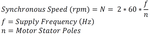
To avoid an involved discussion of the principles of operation for AC Induction Motors, the Synchronous Speed can be considered as an approximation of the shaft speed when the motor runs without any load. The Synchronous Speed can be calculated using the equation below which has just two variables – number of motor stator poles and supply frequency.
Harmonized national standards for mains electricity supply in North America means the Supply Frequency for an AC Induction Motor directly connected to mains can effectively be assumed to be 60 Hz. For this reason, North American industry often identifies motor designs by their synchronous speed when powered by a 60 Hz supply. The table below details the Synchronous Speeds for common AC Induction Motor designs supplied by 50 Hz and 60 Hz mains supplies.
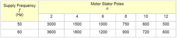
Table 1- Synchronous Speed for Common AC Induction Motor Pole Counts, Supply Frequencies
The Synchronous Speed is effectively the “No Load” shaft speed of an AC Induction Motor. In reality, the “No Load” shaft speed of the motor will be nominally smaller than this value – typically a couple of RPM's less than values in Table 1.
Consider an unloaded AC Induction Motor running near the Synchronous Speed of the motor. When a load is applied to the same motor the shaft speed will slow (“Slip”) in proportion to the size of the load. If the magnitude of the applied load is equal to the nameplate Rated Power of the motor the shaft speed will slow to the motor nameplate Rated Speed.
This behaviour of AC Induction Motors under changing load conditions is as we might expect: As the load demands more power the motor shaft speed slows down. Conversely if the load on the motor is reduced the shaft speed will increase. It is important to understand that the load dictates the motor speed and this concept is illustrated below.

Why should I care about Synchronous Speed and Rated Speed?
Synchronous Speed and Rated Speed are important to consider when developing a specification for an AC Induction Motor for a new, replacement, or retrofit application. A basic understanding of these concepts will allow you to better interpret the information marked on AC motor nameplates. For example, a customer might send you the request below:
“Can you quote me a 3600 RPM, 460 V, 7.5-kilowatt motor?”
If we assume the supply frequency is 60 Hz and refer to Table 1 this is equivalent to asking:
“Can you quote a two pole, 460 V, 60 Hz, 7.5-kilowatt motor?”
The questions above define the bare minimum information required by the Inside Sales team at Lafert North America to quote a motor as the supply voltage and frequency, the output power and (directly or indirectly) the motor stator pole count are defined. The nameplate of one motor design resulting from the RFQs is shown below.
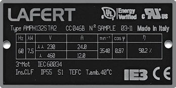
Figure 1- 2 Pole, 460 V, 60 Hz Motor Nameplate
The two pole motor nameplate above indicates the Rated Speed (“min-1”) of the motor at 60 Hz is 3540 RPM. Referring to Table 1 above we see the Synchronous Speed for a two pole motor at 60 Hz is 3600 RPM. The 60 RPM difference between values is due to the amount of “Slip” which is required to develop the Rated Power of 7.5 kW.
It is common practice for catalogues, manuals or computerized inventory systems to organize or advertise induction motors using the Synchronous Speed. This approach is sensible in most cases as the small differences between Rated Speed and Synchronous Speed will not have a significant effect on the majority of AC motor applications. However, there are some applications where small changes in the motor speed under load can affect system performance.
As minimum requirements for electric motor energy efficiency continue to increase, it is important to note that high efficiency motor designs (i.e. NEMA Premium) tend to have reduced Slip relative to their lower efficiency predecessors. The corresponding increase in Rated Speed can affect system performance and should be considered when replacing less efficient motors. Particular attention should be paid when replacing motors which drive centrifugal pumps/fans.
Executive Summary
-
The Synchronous Speed of an AC Induction Motor is the approximate speed at which the motor shaft will turn under no load. This value can be calculated easily using the supply frequency and the quantity of motor poles.
-
Increasing the load applied to an AC Induction Motor will cause the shaft speed to “Slip” to some value less than the Synchronous Speed but greater than or equal to Rated Speed. The Rated Power is delivered at Rated Speed.
-
In industry parlance “Slip” is defined as the difference between the motor shaft speed and the calculated Synchronous Speed (in RPM or % of synchronous speed). The Slip increases/decreases in proportion to the load.
- The Rated Speed marked on Lafert motor nameplates is the shaft speed of the motor when delivering Rated Power to a dynamometer load under factory laboratory conditions. The Rated Speed for a given motor design type is applied to all motors of that type produced. This is consistent with NEMA and IEC motor standards.
Matthew Temple, Outside Sales - Lafert North America
Keys to Selecting the Proper Motor...
The best way to identify a motor is to get a photo of the nameplate. That’s where you’ll find information that leads to a quick and easy identification. A quick picture of the plate and overall motor (focused on output shaft and flange), allows our sales team the opportunity to quickly provide an estimation on your customer’s requirement.
So, to simplify the process for yourself and your customers, look to provide these key 8 points;
1. A photo of the name plate on the motor
2. A photo of the motor
a. From multiple angles where possible
b. Insure good shot of Output Shaft and Flange
3. Is there a flange?
a. Type of Flange; B5 “D” flange or B14 “C” Flange
b. What is the size of flange, Increasing, Reducing or Standard
c. BC and OD on bolts
4. Power Supply to Motor
a. Are 3 power lead or a 6 power leads, brought to motor?
b. 3 Phase or single phase
5. Motor Starting
a. On/off switch – direct across the line start
b. Soft Starter
c. Wye/Delta Start
d. Controlled Starting
6. Physical and Environmental Consideration
a. Exposure to an ambient temperature in the range of 0º to 40ºC
b. Exposure to an altitude which does not exceed 3300 feet
c. Indoor or outdoor use
d. Wash down environment
e. Chemical duty
f. Explosion proof
g. Etc.
7. Is it a brake motor?
8. High reversing application or cycling application
The more information you can provide, the quicker we can respond with a precise drop-in motor replacement, that meets the customer’s requirements and your needs.
.John Ainsworth, Inside Sales Representative - Lafert North America
For a detailed list of key points to ordering a Flameproof Motor, see/download our Lafert Product Catalogue 2018-2019: page 32
 SITI Gear is an Italian manufacture of high-quality and diverse industrial gear reducers represented by Lafert North America.
SITI Gear proudly presents the following did you know…?
Did you know there are two primary considerations for selecting the correct gear oil for an application?
GEAR SPEED
High velocity applications such as mixers, high speed conveyors and even positive displacement pumps are generally associated with light loads and have a very short contact time between the gear teeth. For these types of applications, a low-viscosity oil is usually adequate.
Viscosity, by definition, is an oil's resistance to flow and shear.
In contrast, low speed applications such as shredders and winches are associated with high loads, therefore tooth engagement have longer contact times. These conditions require higher viscosity oils. EP (extreme pressure) additives may be required if the loads are very high.
TEMPERATURE
Ambient and operating temperatures are also a large determining factor in the selection of gear lubricants. Normal gear oil operating temperatures range from 90F to 100F (50C to 55C) above ambient. Oils operating at high temperatures require an appropriate viscosity and high resistance to oxidation and foaming.
Caution should be exercised with abnormally high temperatures. High operating temperatures of a gear reducer may indicate the oil could be too viscous for the application. This means the film of oil on the gear teeth is too thin and friction is the cause of the heat, there could be an excessive amount of oil in the housing, or perhaps an overload condition is occurring. Each of these conditions should be investigated to determine the cause and to correct the problem.
For low ambient temperatures, oils must be able to flow easily and provide adequate viscosity. Therefore, these gear oils must possess high viscosity indices and low pour points.
*From: www.agroengineers.com/gears/gears-lubrication.shtml.
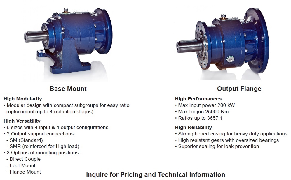
Planetary Gearbox Features - NRG Series
SITI RIGHT ANGLE WORM REDUCERS
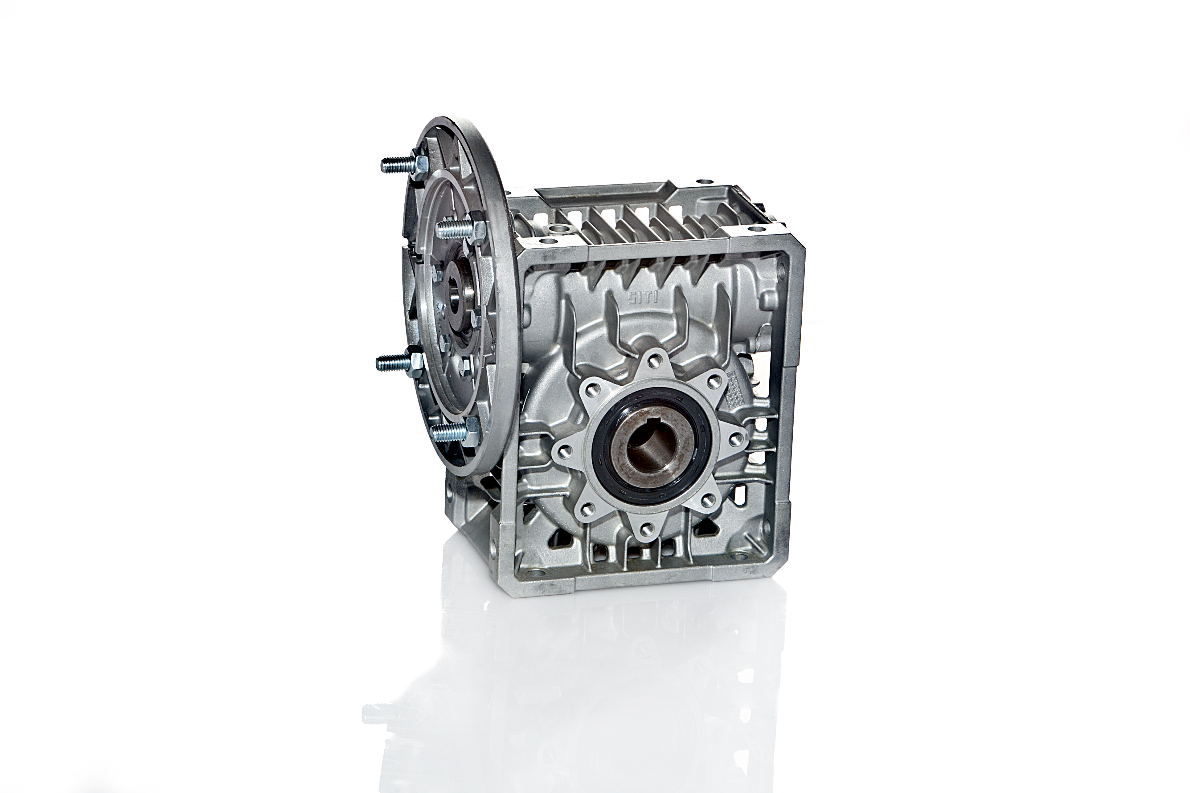
The SITI MU Series of worm gear reducers provide customers with a maintenance-free gearbox offering 20,000 hours of bearing life and 200,000 hours of gear life. As a standard, these gear reducers are provided with Omala VG320 synthetic-lube, which will outlast the life of the unit when installed in normal ambient temperature applications.
Lafert NA Offers a Variety - COOLANT PUMPS
Did you know that Lafert offers a variety of Coolant Pumps, with capacities of up to 1,200 l/ min, head up to 10 bar?
The body can be constructed of steel, cast iron, aluminum, brass or plastic for industrial applications and mainly for use in cooling, lubrication, washing and air-conditioning plants or anywhere where water-oil emulsions and pure cutting oils are needed, with flow rates reaching 1,200 liters/min. and head of up to 100 meters.
In particular, stem pumps are designed from the point of view of reliability, reasonable running costs, user safety and total elimination of risks of the pumped liquids overflowing or leaking.
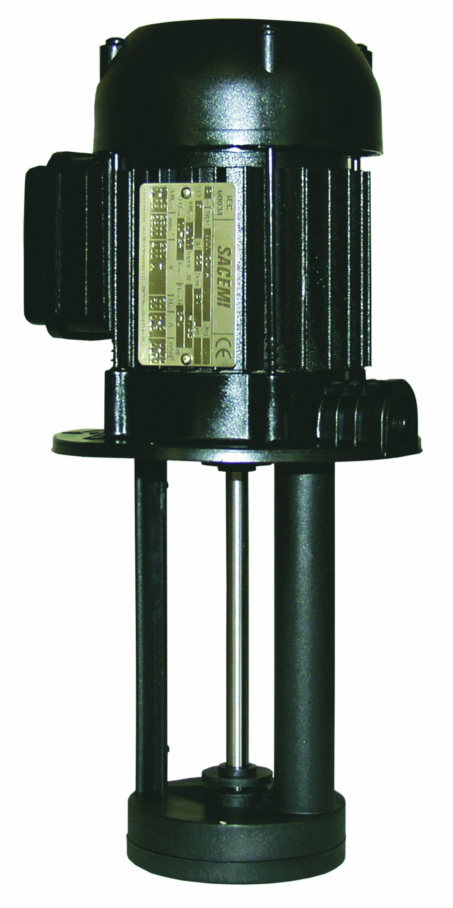
The electric pumps are fitted with 2-pole electric motors, closed construction, with cast aluminum alloy body and vertical axis, cooled by external ventilation with class-F (class-H on request) winding and level IP55 protection in compliance with IEC 34-5 standards.
Pumps can be supplied with three phase or single phase motors. Special voltages and thermal protection is available upon request.
The terminal board cover is fitted with cable connections in compliance with international standards; these can be orientated over 360°, on request. It can also be supplied in a pressure-cast aluminum alloy or with an incorporated switch.
Rigid radial, double screen, pre-lubricated ball bearings are used, produced by the main European manufacturer Sacemi.
Contact a Lafert NA sales representative for more information on the model and type of pump that is suitable for you.
Coolant Pump Design & Applications
The conventional “Coolant Pump” is used in a variety of applications extending far beyond the machine tool industry. However, machine tool applications are still the primary installation base for the product.
Below is a quick reference for applications and key points when specifying a pump.
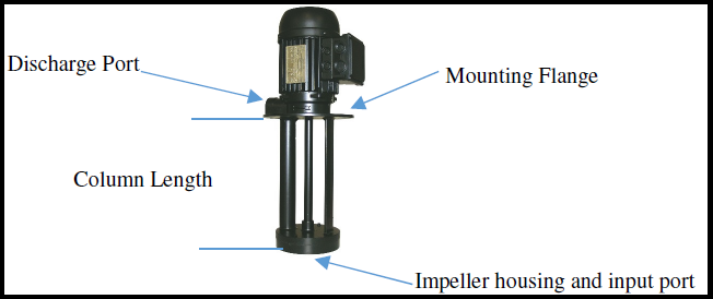
Immersion Style Coolant Pump – SPV Series - The Basics
The pumps are installed on the top of the coolant tank supported by the mounting flange, with the column submerged into the cutting fluid. This pump series has an opening at the bottom of the impeller housing and the rotating impeller will draw fluid in and pressurize it in an oblong cavity. This pressurized fluid is then pushed through the discharge tube and up the discharge port located above the mounting flange.
The amount of fluid and the pressure at which it is delivered will be determined by the Horsepower rating of the pump and the size or quantity of the impeller utilized to build pressure. The standard design pump has one impeller, however for higher pressure applications multi-stage impeller systems are available.
Performance charts are available, which show a height (Head) in meters to correspond flow rate for each pre-set height. The viscosity or thickness of the fluid being pumped will also play a part in the volume and pressure at the delivery point. The pumps are designed for a maximum fluid viscosity of 21 cst.
When sizing a pump, you should consider the following key points: 1) The Horsepower required to deliver the desired flow of fluid at the required head. 2) The physical dimensions of the mounting plate and whether it will mount on the tank. 3) The length of the column, meaning how far down into the tank the impeller needs to be. It is important not to have the pump on or near the bottom of the tank (to avoid having the cutting residual being drawn up into the pump). Conversely, If the impeller is not positioned deep enough into the tank, there will be no circulation. Some reservoir tanks will have a screen which covers the column in the tank to prevent excess machined cuttings from entering the pumping cavity as a filtering method.
Applications:
-
Machine tools
- Milling Machines, Lathes, Drills
- Glass processing Machines
- Printing machines
- CNC Machines
- Air Conditioning Systems
- Filtration systems
Click here for the Coolant Pump designs we offer, or contact one of our sales representatives for help in distinguishing which pump you need.